Do not worry!
You were not confused of video.
My name is Gastón.
I am from channel Projectos LED.
And this is a super special video,
collaborative with Ampletos.
It's a my design,
that he masterfully led to life.
I'll leave my video here,
on the cards,
where we tested on the protoboard
Now I leave with full the practical part,
and the final assembly of this vu-meter
with built-in microphone.
Many thanks Gastón
howdy friends!
Excellent VU-meter of Projectos LED
I did basically a development
From a PCB to my style,
and fit it this way
To give you a practical application.
For example:
To use as decorative in video jukeboxes
This is already in everyone.
Let's continue with the assembly.
Construya su videorockola
VU-meter activated by microphone
Next you will watch how to build
a very striking vu-meter,
which can use as decorative.
Materials
Printed circuits boards.
The first PCB is the controller card,
and the second PCB is the LED panel.
You can learn them to do,
with the help of our tutorials.
A integrated circuit LM3915,
with its base of 18 pins.
A regulator LM7805.
A transistor BC548.
A diode 1N4007.
A fast-swiching diode 1N5819 or 1N4148.
A electret microphone.
A 1K rheostat.
Three 0.47uF capacitors.
A 0.33uF capacitor.
A 0.1uF capacitor.
Two 10K Resistors.
Three 100K Resistors
A 1.8K Resistor.
Two 2.5 mm 3 pin MOLEX connectors.
A 2.5 mm 2 pin MOLEX connector.
A jumper used on the computers motherboard.
30 LEDs of 5 or 10 millimeters.
In this case we use 15 green LEDs,
9 yellow LEDs
and 6 red LEDs.
A plastic box 17 centimeters long,
7 centimeters high,
and 3.5 centimeters thick.
Also with its respective cover.
If you do not get it,
you can do it with the molds
that we provide in the PDF file.
A piece of transparent acrylic hammered,
from 16 by 6.3 centimeters.
A piece of red and black polarized cable,
from 12 centimeters long.
And a piece of ribbon cable of 12 colors threads,
from 10 centimeters long.
Tools
Welding of tin
A 30 Watts soldering iron.
Scalpel
Thin-tipped tweezers
Hand drill with a 4 milimeters drill bit
Silicone gun with its bar
Wire Stripper
Scissors
Thinner
Toothbrush
Wirecutter,
if not, can use a nail clipper
And white paint with a thin brush.
assemble
We will begin by place all the resistors.
We take a resistor
Bend the terminals
And it is placed in its respective place in the card.
We do the same with the other 5 resistors.
Check their value very well
before placing them.
It is very important to know how to read
the resistors color code.
So that the resistors do not leave their place,
they bend their terminals slightly outwards.
And proceed to weld all the resistors.
Remember that the correct way to weld,
is done, joining welding,
soldering iron and piece to weld,
at the same time.
Cut all the terminals excess,
with the aid of the nail clippers.
Now place the 1N4007 diode
and the 1N5819 diode.
Bend the diode terminals
And place it in the PCB,
keep in mind the direction shown
in the component mask.
Do the same with the other diode,
bend its terminals
And place it in its respective place,
check carefully.
Separate the terminals so that they do not come out
when turning the PCB.
Proceed to weld.
The welds should be round and shiny.
And cut the excess of the terminals.
Now place the integrated circuit base
respecting the direction
shown in the component mask
And weld it.
Be very careful not to join the points
with excess welding.
Now proceed to place the 3 capacitors of 0.47uF
They stand straight and slightly raised
of the PCB surface.
Continue with the 0.33uF capacitor.
To finish installing the capacitors,
place the 0.1uF capacitor.
Proceed to weld all capacitors.
Next, place the BC548 transistor.
You must keep in mind the position
shown in the component mask.
And weld them.
Now come to place the 1K rheostat
It is placed in its place
And weld it.
Continue with the connector that holds the jumper.
Place it in their respective place
place the jumper
And weld the connector.
Now place the microphone
and the power input connectors.
Remove the center pin of the male connector.
Place the connector that allows
to connect the microphone away from the PCB
And the power input connector.
We welded.
Next, place the LM7805 regulator.
It must be placed in the correct position.
We weld it
And cut the excess of the terminals.
To complete assembly of the controller card,
place the LM3915 IC.
It must be positioned in the correct direction.
We have the card that controls the LEDs ready
Now have to assemble the LED panel.
Each LED is placed in its place,
respecting its polarity.
In case an LED is inverted
it will not turn on the entire row.
The color distribution is made to taste,
as is the size of the LEDs.
You can use LEDs of 5 or 10 millimeters,
as long as they do not exceed a consumption
of 30 milliamps.
Weld all the LEDs.
The welds must be of good quality.
With the aid of the nail clippers,
cut all the excess of the terminals of the LEDs.
Now, take the colored cable ribbon
and with the aid of the scalpel,
separates each cable.
We must be careful
not to cut the plastic covering the wires.
Make a straight cut,
so that the tip cables are straight.
And with wire stripper,
removes about 2 millimeters
of insulated from each of the cables.
Proceed to weld the tip of each cable.
Must use the minimum of welding.
Now, introduce each cable
into each hole in the LED panel
And weld each wire.
Remember to make good welds,
and avoid union the one point with the other point.
Next, wet the toothbrush with thinner
And wash the card very well,
on the side of the tracks.
This is done to remove the grease,
and any particles of dirt
and solder that may have remained.
Dry the card with a piece of toilet paper
And finish cleaning with a dry brush.
The card should be perfectly clean and shiny.
Do the same with the controller card.
A good cleaning ensure the smooth operation of circuit.
Now measure the LED panel in the box,
and we calculate where the hole through
which the cables will go.
Make two perforations at the top of the box,
And with the scalpel,
cut from a hole to the other hole,
until get to the other side of the plastic.
Check that the card fits snugly
when pulling the cables through the hole.
In order to take full advantage
of the light emitted by the LEDs,
must paint the edges of the interior of the box.
This helps to reflect the light emitted by the LEDs,
towards the front of the box.
Can use white or silver paint.
After the paint has dried,
introduce the LED panel into the box.
Separate the wires from the other end of the ribbon,
With scissors, the cables are paired
Removed 2mm of plastic from each wire.
And apply weld to the cables tips
taking into account not exaggerate the amount of welding.
Each wire is inserted into each hole
in the controller card.
Must be maintained the same order that comes
from the LED panel.
They are welded one by one,
wires to the controller card.
Make good welds.
Having everything properly welded,
apply hot silicone
at the cables junction with the card.
This is done to avoid future fractures in the joints.
Now, apply hot silicone to the back of the box
And paste the controller card
keeping in mind that it is well centered.
Can use hot silicone to secure the LED panel.
Apply small dots.
Next, place the microphone.
To do this,
take the red and black polarized cable,
and separate both wires.
Peel the tips about two millimeters.
Welding is applied on both tip ends
check the positive pole
And what is the negative pole
of the electret microphone.
Weld the cables,
keep in mind the polarity.
Also separate the tips at the other end of the cable
Remove 2mm of insulation
And welding is applied.
Apply welding on the metallic nails
of the female terminals.
And we weld the nails with the wires.
We do this in this way,
thinking of people who do not have a crimping tool.
Close the fins of the terminal,
pressing on the wires.
Insert the metal nails into the female terminal.
The female connector connects to the male connector,
where the microphone goes,
on the card,
Hold the microphone to the box,
using hot silicone
The microphone should look face,
the front of the box.
Feed the VU-meter with a 12 volt DC,
and at least one ampere.
One two three four
Testing our vu-meter with microphone
All right!
It works perfect.
Now let's put the lid on.
Open 4 holes,
one at each end of the lid.
Carefully cut through the inside edge of the lid
aside from the bezel.
The scalpel should be slid many times,
until it passes to the other side.
Sometimes it is necessary to grate with the scalpel
over the other side of the lid.
We already have a frame ready made
from the lid of the box.
Put the transparent acrylic
to the edge of the mouth of the box
And place the frame, to give the final finish.
Good friends!
We already have our vu-meter ready
As you can see,
they can do it with LEDs of 5 millimeters
or with LEDs of 10 millimeters.
It depends on your taste
The colors can also choose you,
those that you consider.
We hope this project will be of great use to all of you.
Remember to also visit the
Proyectos LED channel
Greetings to all.

 For more infomation >> В Сети высмеяли полупустой зал "Евровидения 2017" (10.05.2017.) - Duration: 1:17.

 For more infomation >> Live Stream Playing Battlefield 1 With (Face Cam) - Duration: 3:52:58.

 For more infomation >> {CASH OUT) 0.00121843 Satoshi !!! Wait 1 - 3 Hours !!! Payment With Proof Update 10/05/2017 - Duration: 2:51.
  For more infomation >> 10 ИНТЕРЕСНЫХ ФАКТОВ ПРО ТАДЖИКИСТАН - Duration: 5:25.
  For more infomation >> RPG level 2 - BiTS - ARTE - Duration: 12:24.
  For more infomation >> Por que a lã das ovelhas não encolhe na chuva? | Minuto da Terra - Duration: 1:45.
  For more infomation >> 護膚! 瘦臉! 妝物! 零食! 電影等等一大堆🎀 近日最愛的它它它 (中字)|My Current Favorites | Lizzy Daily - Duration: 10:44.
  For more infomation >> The Guild: Origins - BiTS - ARTE - Duration: 5:10.
  For more infomation >> Elif Tümen - Kral Takipte Çekimi Öncesi Ve Kamera Arkası - Duration: 3:44.
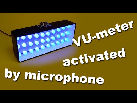


Không có nhận xét nào:
Đăng nhận xét